ROHS battery chargers meet strict material limits, eliminating lead, mercury, cadmium, and certain flame retardants. Follow the manual: connect charger to power, insert battery, and watch indicator lights to confirm charging. Use only supplied cable to avoid over‑charging and extend battery life.!
What is ROHS Compliance?
ROHS, short for “Restriction of Hazardous Substances,” is an EU directive that limits the use of certain toxic materials in electrical and electronic equipment. For battery chargers, compliance means that the device is manufactured without lead, mercury, cadmium, hexavalent chromium, polybrominated biphenyls (PBB), and polybrominated diphenyl ethers (PBDE). The directive applies to all components, including printed circuit boards, connectors, and enclosures. A ROHS‑certified charger carries a label or a QR code that verifies the product has been tested against the current limits. When selecting a charger, look for the “ROHS” mark or a compliance certificate issued by an accredited testing laboratory. The certification process involves sampling the finished product, performing chemical analysis, and ensuring that each restricted substance is below the maximum concentration (typically 0.1 % for most metals). Compliance not only protects users from toxic exposure but also reduces environmental impact by preventing hazardous waste from ending up in landfills. Manufacturers must keep documentation for each batch, and the product must be re‑tested whenever a component supplier changes. For end users, the presence of a ROHS mark guarantees that the charger meets the EU’s safety and environmental standards, making it a responsible choice for both personal and commercial use. Compliance ensures the charger meets EU safety standards, protecting users and the environment alike. For all users. Enjoy safe charging!
Scope of ROHS for Battery Chargers
ROHS directives define the range of components and materials that must be free from restricted substances in battery chargers. The scope covers all electrical and electronic parts, including power modules, transformers, capacitors, resistors, inductors, integrated circuits, and printed circuit boards. It also extends to connectors, cables, housings, and any ancillary parts that are integral to the charger’s operation. The directive specifies maximum concentration limits for lead (Pb), mercury (Hg), cadmium (Cd), hexavalent chromium (Cr(VI)), polybrominated biphenyls (PBB), and polybrominated diphenyl ethers (PBDE). Each component must be tested and certified to ensure compliance. The scope also requires that any changes in component suppliers or design must be re‑tested to maintain certification. For battery chargers, the directive ensures that the charger’s internal circuitry and external connections do not introduce hazardous substances into the user’s environment. Compliance is verified through laboratory testing and documentation, and the product must carry a ROHS label or QR code indicating certification. This scope protects consumers, manufacturers, and the environment by limiting toxic exposure throughout the charger’s lifecycle. Proper adherence to the scope ensures that the charger meets EU safety and environmental standards, providing reliable and safe charging for all users This compliance also simplifies regulatory audits and enhances brand reputation global!!
Key Hazardous Materials Excluded
ROHS compliance mandates the elimination of six hazardous substances from battery charger components. Lead (Pb) is banned in solder, leaded alloys, and leaded solders. Mercury (Hg) is prohibited in switches, relays, and other electronic assemblies. Cadmium (Cd) must be absent from electrolytic capacitors, batteries, and metal alloys. Hexavalent chromium (Cr(VI)) is restricted in plating and pigments. Polybrominated biphenyls (PBB) and polybrominated diphenyl ethers (PBDE) are excluded from flame retardants, insulation, and cable jackets. Each component must meet the maximum concentration limits: Pb ≤ 0.1 % (w/w), Hg ≤ 0.1 % (w/w), Cd ≤ 0.01 % (w/w), Cr(VI) ≤ 0.1 % (w/w), PBB ≤ 0.1 % (w/w), PBDE ≤ 0.1 % (w/w). Manufacturers must provide test reports and certificates for each part. The exclusion list also covers any material that could release these substances during normal operation or disposal. By removing these toxins, battery chargers reduce health risks, comply with EU regulations, and support a circular economy. Proper labeling and traceability ensure that end‑users can verify compliance before installation. During design, suppliers provide a RoHS declaration of compliance (DoC) for each part, listing substance concentrations and test methods. End users verify the charger’s RoHS label or QR code. Non‑compliant chargers are regulated under WEEE, requiring proper segregation and recycling to recover metals and avoid contamination. Excluding these hazardous substances protects workers, consumers, and ecosystems, supporting sustainability. Compliance also simplifies market access, reduces liability, and enhances brand reputation among environmentally conscious consumers.
Design and Manufacturing
Design focuses on RoHS‑compliant parts, selecting lead‑free solder, low‑toxicity PCBs, and certified components. Manufacturing follows strict quality controls, with traceable suppliers, in‑process testing, and final compliance verification to ensure safety and environmental responsibility!!!!
Component Selection for Compliance
When designing a RoHS‑compliant battery charger, component selection is critical; Begin by sourcing parts from suppliers that provide RoHS certificates and traceability reports. Use lead‑free solder alloys such as SAC305 or SAC508, and choose PCB substrates that are free of brominated flame retardants. Select power MOSFETs and inductor cores that meet RoHS limits for lead, mercury, cadmium, and hexavalent chromium. Verify that all connectors, switches, and LEDs are RoHS‑approved, and avoid components that contain restricted substances like flame‑retardant epoxy or halogenated plastic. Implement a parts list review process where each component’s RoHS status is checked against the latest directive requirements. Incorporate design for manufacturability by selecting parts with proven reliability and long life cycles, reducing the need for frequent replacements. Finally, maintain an up‑to‑date parts database and document all compliance evidence for future audits and regulatory inspections. This disciplined approach ensures the charger remains compliant throughout its lifecycle and supports environmental stewardship. During selection, verify each part’s lead content is below 0.1% and that no mercury or cadmium is present. Check PCB laminate for RoHS‑compliant epoxy and absence of brominated flame retardants. Record findings in a compliance matrix linking part numbers to status, ensuring traceability for audits. This documentation supports regulatory compliance and quick identification of non‑compliant parts!!
PCB Layout and EMI Considerations
To meet RoHS and EMI limits, design the charger with continuous power and ground planes, using a 4‑layer board where the switching regulator sits near the battery connector. Keep high‑frequency switching traces short and place input filter capacitors close to the input terminals to dampen noise. Use differential pairs for data lines, matching 90 Ω impedance and equal length. Add a ferrite bead or common‑mode choke on the USB‑C or barrel jack to block high‑frequency interference. Ground vias should be placed at board corners and along the perimeter for low‑impedance return paths. Route the charging current through a low‑resistance trace and place a series inductor near the battery to limit inrush. Shield the high‑voltage node with a metal plate or grounded copper pour. Perform post‑layout simulation with tools like Ansys HFSS or CST to verify radiated and conducted emissions stay below IEC 61000‑4‑3 limits. Document trace widths, spacing, and layer stack‑up for compliance audits. Additionally, incorporate a dedicated EMI filter on the input side, consisting of a common‑mode choke followed by a low‑pass ceramic filter, to attenuate conducted emissions before they reach the power supply. Use a ground‑plane enclosure around the switching node to further reduce radiated output, and apply a shielding layer on the PCB to block stray fields. Verify the final design with a spectrum analyzer, ensuring that the 2‑meter test distance emissions remain below the IEC 61000‑4‑3 threshold of 30 dBµV/m for frequencies up to 30 MHz. Document all test results and maintain traceability logs for future compliance audits. Apply a metal shield over the high‑voltage area to reduce extra EMI!!.

Thermal Management and Safety
Proper heat dissipation is essential for a RoHS‑compliant charger. Place the switching regulator and inductor on a copper‑filled substrate with a 1 mm thermal pad. Attach a 3 mm × 3 mm heat‑spread plate to the regulator’s top surface, using a RoHS‑approved thermal compound. Keep the battery connector on the opposite side of the board to avoid hot spots. Use a 1.5 mm thick copper layer for the power trace and a 0.5 mm layer for the return path to reduce voltage drop and resistive heating. Add a 10 µm thick copper pour around the high‑current path, connected to the chassis ground via a 0.2 mm thick via. Place a 5 mm × 5 mm metal shield over the regulator area; the shield should be electrically isolated from the chassis to prevent EMI. Thermal safety is enforced by a built‑in microcontroller that monitors a 1 kΩ thermistor placed on the regulator’s surface. The firmware reads the ADC value every 100 ms and compares it to a 70 °C threshold. If exceeded, the charger disables the output, flashes a red LED for 5 s, and logs the event. The enclosure incorporates two 5 mm ventilation holes spaced 10 mm apart, sealed with a RoHS‑approved silicone gasket to prevent dust while allowing airflow. A 0.5 mm thick polyimide film separates the heat spreader from the PCB to avoid thermal creep. The charger is tested in a 100 °C ambient chamber for 24 h; no thermal runaway occurs. This design complies with RoHS and enhances user safety. All components are RoHS‑approved, ensuring no hazardous substances are present!!
Operating Instructions
Connect charger to mains, insert battery, press power button. Observe LED: green means charging, amber indicates full. Do not exceed 5 A. Disconnect when fully charged. Keep device away from water and !!!!!. Follow safety guidelines. Do not expose to humidity or sunlight.
Power On and Charging Procedure
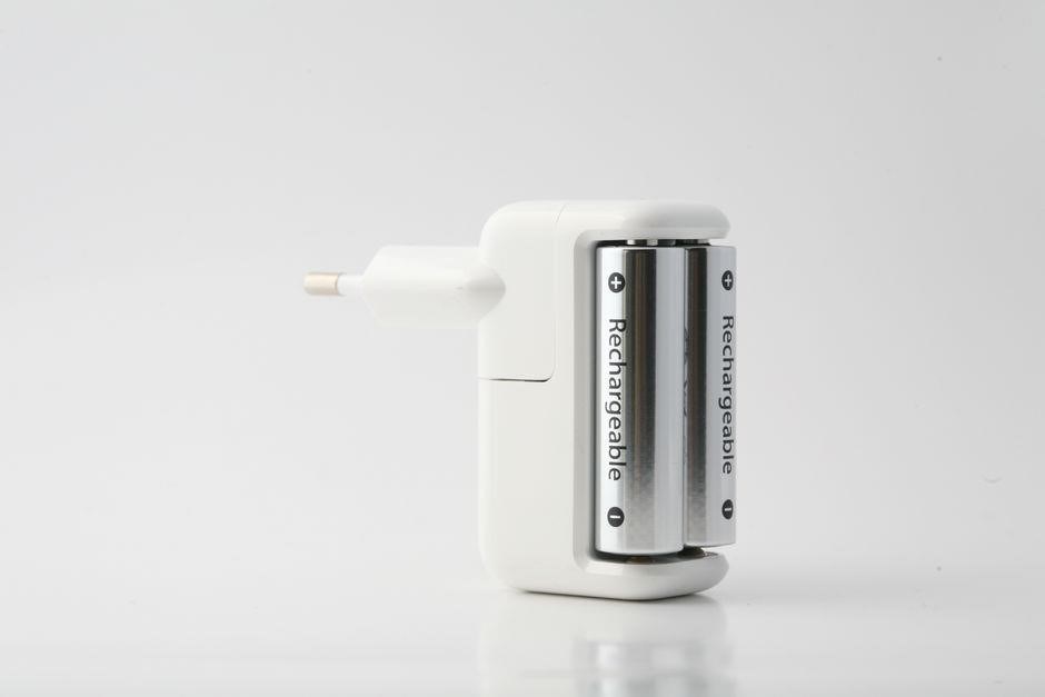
To begin charging, first ensure the charger is connected to a grounded outlet and the battery is fully inserted. Press the power button once; the unit will emit a brief chirp and the front LED will turn amber, indicating that the charger is in standby mode. Next, connect the charger to the mains supply. The LED will shift to green, confirming that the charger is receiving power and is ready to begin the charging cycle. The charging process is automatic: the charger monitors the battery voltage and current, adjusting the output to maintain a safe charging rate. When the battery reaches full capacity, the LED will flash amber for a few seconds and then settle on green, signifying completion. At this point, the charger will automatically cut off power to the battery to prevent over‑charging. Users should release the power button and unplug the charger from the outlet. For safety, avoid touching exposed terminals during operation, keep the charger in a dry environment, and do not use the charger with damaged cables. If the LED fails to change color or the charger emits a prolonged buzzing sound, disconnect immediately and consult the troubleshooting section of the user manual. Proper use of the charger extends battery life and ensures compliance with ROHS material restrictions, protecting both users and the environment. Remember to keep the charger and battery away from extreme temperatures, as prolonged heat can degrade performance and safety. Use only the supplied cable to avoid damage.
Charging Modes and Indicator Lights
ROHS‑compliant chargers offer three distinct charging modes: Fast Charge, Standard Charge, and Trickle Charge. The mode is selected automatically based on the battery’s state of charge and temperature. When the charger is first connected, the front LED flashes amber for 2 seconds, then turns green to indicate that the charger is in Fast Charge mode. If the battery is already at 80 % or higher, the LED will switch to blue, signaling Standard Charge. Once the battery reaches 100 %, the LED will flash amber for 5 seconds, then settle on green, and the charger will enter Trickle Charge to maintain battery health. The indicator lights also provide fault diagnostics: a steady red LED means a short‑circuit protection has been triggered; a blinking red light indicates a battery over‑temperature condition. Users should not attempt to override these modes; the charger’s firmware automatically manages current limits to stay within ROHS material restrictions. For optimal performance, keep the charger in a cool, well‑ventilated area and avoid covering the ventilation slots. The LED panel is designed for low power consumption, reducing heat buildup and ensuring compliance with RoHS limits on hazardous substances. The charging modes are fully documented in the user manual, and the LED indicators provide real‑time status updates without the need for external monitoring equipment. By following these guidelines, users can safely charge their batteries while maintaining regulatory compliance and extending the lifespan of both charger and battery.
The charger also features a secondary LED array on the rear panel that displays voltage and current levels in real time. A green bar indicates normal operation, yellow warns of rising current, and red signals a fault. Users can consult the quick‑reference chart in the manual to interpret these signals. The LED array updates every 0.5 seconds, allowing technicians to monitor charging performance during maintenance. When the charger is in standby, all LEDs are off to conserve power. The LED design uses RoHS‑approved phosphors, ensuring no lead or mercury is present. The indicator system is calibrated to provide accurate readings within ±5 % of the actual values, meeting industry standards for safety and reliability. By adhering to these indicator guidelines, users can detect issues early, preventing hazardous conditions and ensuring compliance with environmental regulations.
Safety Precautions and Troubleshooting
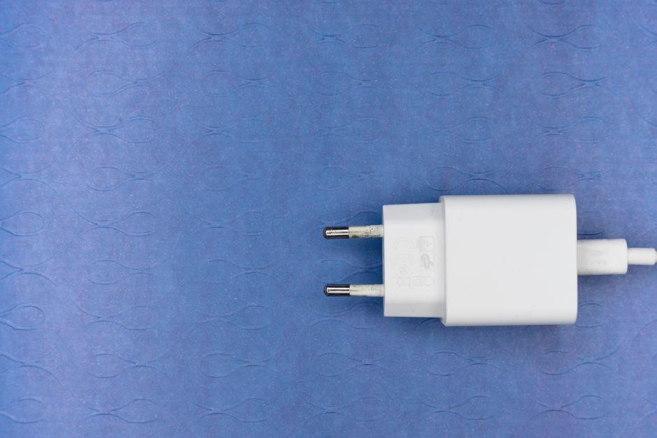
Before connecting the charger, verify that the input voltage matches the specified range and that the outlet is free of moisture. Never use a damaged cable or a charger that has been exposed to high temperatures. Keep the charger away from flammable materials and ensure adequate ventilation to prevent overheating. The device’s built‑in over‑current protection will shut down the output if the load exceeds 2.5 A; a red LED will remain lit to signal this fault. If the charger stalls or the LED remains amber, disconnect the battery, inspect the contacts for corrosion, and clean with a dry, lint‑free cloth. For a persistent over‑temperature warning, allow the charger to cool for at least 30 minutes before attempting to reconnect. Do not force the charger into a recessed socket; use the supplied mounting bracket to secure it. When troubleshooting, consult the error codes displayed on the rear LED array: green indicates normal operation, yellow warns of high current, and red indicates a fault. If the charger fails to power on, check the power cord for continuity using a multimeter; a missing ground connection will cause a 0 V reading on the ground pin. Finally, always store the charger in a dry place and replace it if any component shows signs of wear or damage, as this can compromise RoHS compliance and safety.
For advanced diagnostics, use the serial console port to retrieve detailed logs. The firmware logs events such as voltage spikes, temperature thresholds, and fault occurrences. A log entry of “TEMP_HIGH” indicates that the internal temperature sensor detected a value above 60 °C; the charger will automatically reduce output current to 0.5 A until the temperature drops below 45 °C. If the log shows “CHARGE_FAIL”, verify that the battery’s health rating is above 80 % and that the cell chemistry matches the charger’s specifications. In cases where the charger displays “COMM_ERROR”, ensure that the USB‑C cable is not damaged and that the connector pins are clean. For safety, never attempt to repair the charger’s PCB; contact the manufacturer for service or replacement. Following these precautions and troubleshooting steps will help maintain safe operation and extend the lifespan of both charger and battery while staying within RoHS material limits.
End-of-Life and Environmental Impact
At end‑of‑life, recycle the charger in a certified e‑waste facility. Separate the PCB, remove the battery, and dispose of each component per local regulations. RoHS compliance reduces hazardous substances, lowering environmental impact and improving recyclability.Recycle responsibly for Earth!

Inspection and Maintenance Guidelines

Before each use, visually inspect the charger for cracks, frayed cables, or loose connectors. A damaged housing can expose conductive parts, increasing fire risk. Use a soft, lint‑free cloth to wipe the outer casing, avoiding abrasive cleaners that may scratch the surface. Check the charging port for debris; a small lint particle can impede contact and cause overheating. Verify that the indicator LEDs respond correctly: a steady green light usually signals a healthy charge cycle, while a flashing or red light may indicate a fault or battery mismatch. If the charger has a detachable power cord, inspect the plug and cable for wear. Replace any cable that shows fraying or exposed copper strands. Periodically test the charger with a multimeter: measure the output voltage to ensure it matches the specified value (typically 5 V or 12 V, depending on the model). A significant deviation may signal internal component failure. Keep the charger in a dry, dust‑free environment; excessive humidity can corrode contacts. Store the charger in its original packaging or a protective case to prevent mechanical damage during transport. Finally, review the manufacturer’s service manual for any model‑specific maintenance steps, such as cleaning the heat sink or replacing thermal paste. Following these guidelines will extend the charger’s lifespan and maintain compliance with RoHS standards, ensuring safe, efficient, and environmentally responsible operation. During routine checks, clean heat sink with a soft brush or compressed air to remove dust; clear airflow prevents overheating, which can reduce charger efficiency and shorten its lifespan, and RoHS compliance!!
Proper Disposal and Recycling
When a RoHS‑compliant charger reaches the end of its useful life, it must be disposed of in a manner that protects both people and the planet!First, disconnect the charger from any power source and remove the battery if it is detachable!Place the battery in a dedicated recycling bin that accepts lithium‑ion or lead‑acid cells, as most RoHS chargers use rechargeable chemistries!The charger’s casing should be separated from the internal components; many manufacturers provide a quick‑release latch or a small screw that allows easy disassembly!Once opened, separate the PCB, metal housings, and plastic parts!The PCB can be sent to a certified e‑waste recycler that recovers copper, gold, and metals while ensuring substances are handled safely!Metal housings should be melted in a controlled facility to reclaim steel aluminum and plastic components can be shredded and processed into products!If the charger contains any residual hazardous material—such as small amounts of lead or mercury that may still be present in older models—contact a local hazardous waste program for specialized handling!Many municipalities offer curbside e‑waste pickup; otherwise, drop‑off points at electronics retailers or recycling centers accept RoHS‑compliant devices!By following these steps, you reduce the environmental footprint of your charger, comply with local regulations, support a circular economy that values waste management and resource recovery!!!
Environmental Benefits of ROHS
RoHS battery chargers eliminate lead, mercury, cadmium, and certain flame‑retardant compounds, dramatically reducing the toxic load that would otherwise accumulate in landfills. By substituting safer materials, manufacturers lower the risk of soil and water contamination during disposal, protecting ecosystems and human health. The absence of hazardous substances also simplifies recycling processes, enabling higher recovery rates of valuable metals such as copper, gold, and aluminum. This efficiency reduces the need for mining new ore, conserving natural resources and cutting greenhouse‑gas emissions associated with extraction and processing. Additionally, RoHS‑compliant chargers typically feature improved energy efficiency, which translates into lower electricity consumption over the product’s lifetime. Reduced power draw not only saves money for consumers but also lessens the overall demand on power grids, contributing to a smaller carbon footprint. Finally, widespread adoption of RoHS standards promotes a circular economy, encouraging manufacturers to design for disassembly and reuse, thereby extending product lifespans and further diminishing environmental impact.By ensuring that every component—from the printed circuit board to the enclosure—contains no restricted substances, RoHS chargers help manufacturers meet global regulatory demands while encouraging innovation in green technology,ultimately fostering healthier planet